Key Words: AEM, conductivity, regolith mapping, Tuckabianna, TEMPEST
Recent developments in airborne EM acquisition and sophisticated processing can quantify conductivity and depth. A range of products are now available to exploration geologists. for interpretation. Time domain TEMPEST EM technology is capable of generating subsurface information previously only obtained by either detailed ground geophysics or reconnaissance drilling. TEMPEST is particularly suited to regolith-dominated terrains.
Airborne EM can minimise the risk in exploration drilling by quantifying the depth of weathering to a resistive bedrock. Models of bedrock topography allow prediction of geochemical dispersion patterns, mapping of transported regimes from likely erosional and relict domains in regolith and identification of such features as palaeodrainage, grabens, half grabens, fault scarps and inverted topography. Definition of 3D spatial geometry in the regolith can assist with identification of major regional faults, shear zones and unusual weathering characteristics associated with alteration and mineralisation. Base-metal sulphides and sulphide-associated gold mineralisation can be directly detected by TEMPEST depending on the geometry of the conductor, and the depth and conductivity of regolith. Signatures of known orebodies can be used to identify similar targets in new areas using a simple process of pattern recognition. TEMPEST EM products are ideal for automated prospectivity mapping when integrated with other geophysical, geochemical and geological data sets.
A case history developed for the Comet Gold Mine near Tuckabianna in the Murchison region of Western Australia will demonstrate the most useful data products of TEMPEST and compare different modelling routines. It will also demonstrate a rigorous process of interpretation to develop new conceptual targets for further exploration.
We predict that airborne EM will be the most cost-effective and essential data set in 21st century mineral exploration for both greenfield applications and re-evaluation of well-explored terrains. Information obtained can provide an improved perspective on existing data sets and help generate new targets for follow-up.It is only a matter of time before this technology is responsible for new mine discovery.
TEMPEST airborne EM is the culmination of many years research by CRCAMET, World Geoscience Corporation and CSIRO. The TEMPEST system was developed to combine the capabilities of a high frequency near surface electromagnetic system, (eg SALTMAP) with those of a low frequency sine wave time domain system such as QUESTEM 450.
Surveys were carried out in a variety of environments during its development and interpretation of data from one of these surveys is described in this paper.
Several options in data presentation are now available for interpretation of TEMPEST data. Those most useful are highlighted in a case history, which will describe a TEMPEST survey over the Comet group of mines in the Murchison region of Western Australia.
Airborne electromagnetic surveying is a well established practice in the mineral exploration industry andused extensively in relatively resistive terrains to prospect for base metal orebodies at depth. Conductive overburden has continually posed a problem for exploration in the use of airborne EM to detect conductors below surface. Developments in airborne EM have either improved the penetration of the regolith to map conductors at depth or focussed on the regolith itself to map near surface salinity.
Time domain EM systems, such as QUESTEM 450 and GEOTEM, employ very large transmitter loops and are designed to penetrate the regolith using lower frequencies and greater transmitter moment. These fixed wing EM systems are capable of conductor discrimination and geological mapping in relatively difficult conductive conditions. However, they are limited in extreme conditions such as salt lake environments. Limitations of airborne EM in detection of a strong pyritic conductor at Walford Creek, Queensland, to depths in excess of 150m were discussed by Webb and Rohlach (1992).TEMPEST airborne EM data were collected over Walford Creek and succesfully modelled to depths in excess of 300m, (Lane, 1999). The application of QUESTEM airborne EM to geological mapping in the Mt Isa region was previously described by Anderson, et al (1993). Airborne time domain 37.5Hz QUESTEM EM was also used to map regolith or near surface conductivity (salinity) using the earliest window times (Anderson and Street, 1994).
The square wave time domain EM system, SALTMAP was developed from joint research over the past decade by World Geoscience Corporation, CSIRO and CRCAMET (Duncan et al, 1993). SALTMAP was used on a regional basis over many agricultural districts of Western Australia for the purpose of implementing land care strategies to combat the spread of salinity and land degradation (Street, 1992).
More recently SALTMAP surveys were flown in the Eastern Goldfields at Lawlers and a role for airborne EM beyond direct target detection was noted by Worrall et al (1998). EM was found a good alternative to aeromagnetics for mapping lithogy and structure in covered terrains, where rocks are magnetically quiet. SALTMAP (QUESTEM SW) surveys were carried out over several known gold deposits in the Laverton area. EM data products were used to map regolith, estimate depth to bedrock, assist regional litho-structural interpretation identify discrete responses associated with known alteration and gold mineralisation and generate new targets for exploration (Leeming et al, 1998).
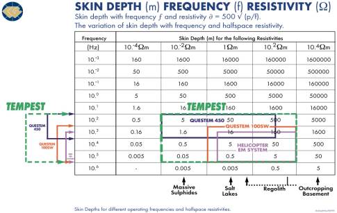
The TEMPEST airborne EM system is the end product of research refining the acquisition, processing and modelling of EM datafrom both the QUESTEM 450 and SALTMAP systems. It provides the significant advantages of broad bandwidth and low noise (Lane et al., 1998). The table below illustrates the improved bandwidth and resolution of TEMPEST compared with other airborne EM systems in a variety of geological environments.
TEMPEST airborne EM data are processed with routines designed to suppress sferic, powerline,VLF and coil motion noise and to stack the data. Stacked data are deconvolved using the high reference waveform, the primary field is removed and the ground response or secondary field data are transformed to B field response for a perfect 100% duty cycle square wave.The 1500 samples per half cycle are binned to 15 windows.
The raw windowed data are corrected for variation in transmitter loop (Tx) terrain clearance, Tx pitch and roll and transmitter-receiver (Tx-Rx) geometry variation, (Lane, 1999) Both raw and corrected data are then available for applying modelling routines to assist interpretation.
Two modelling routines are best suited for airborne EM interpretation by geoscientists. Products generated by a layered earth inversion (LEI) technique (Sattel, 1997) and a conductivity-depth imaging (CDI) algorithm (Macnae et al,1998) are presented in the following case history.
The LEI model is applicable to many covered terrains. A three-layer model with a conductive layer sandwiched between two resistive layers is most appropriate for airborne EM. Layer 1, a thin resistive surficial layer can be hardpan, alluvium and/or colluvium. Layer 2 represents the intervening transported and saprolitic clay and layer 3 is resistive bedrock. Inversion models do not perform as well in areas of extreme (high or low) total conductance. Some extremely high conductance (>200S) environments have been surveyed in which the skin depth limit for TEMPEST has been reached
In resistive or outcropping areas EM data are better modelled using the CDI inversion since the three layer model is no longer valid. Caution must be exercised in the processing and modelling of airborne EM data. Models are only meaningful for conductivity depth information if based on rigorous sampling per interval (eg for TEMPEST 1500 samples per transient compared with 256 for QUESTEM 450 and 125 for SALTMAP).Products available for interpretation, in addition to magnetic and digital terrain data include the following:–
Conductivity depth sections LEI or CDI
“Conductive Unit” Parameters Gridded model (LEI or CDI) parameters summarising depth-to-top, depth-to-base, elevation-of-top, elevation-of-base, thickness and conductance of conductive units identified in 1D models.
Principal Component Images – Principal component analysis to summarise the decay and spatial characteristics of window amplitude data.
Interval conductivity slices – Slices of the average conductivity for intervals below surface.
(eg 0-5m, 5-10m, 10-20m, 20-40m, 40-80m, 80-120m, 120-200m etc)
3-D spatial models may be developed and explored in vertical or horizontal perspectives and rotated to assist selection of the most useful data sets (Lane, 1999). Examples of some of the above data sets are presented in the following case history. Interpretation requires selection of the most appropriate data products and integration of these with other geophysical and geological data.
The Comet open pit gold mine belongs to the Tuckabianna group of gold deposits and is located 25 kilometers south east of Cue in the Murchison Mineral Field of Western Australia. The exploration, mining history and geology of the deposits has been described by Smith (1998). The Comet and associated gold deposits (Comet North, Pinnacles, Eclipse and Venus) are principally hosted by iron-rich sediments within mafic and ultramafic volcanic and intrusive rocks and lie west of the Tuckabianna Fault or Shear Zone.The gold deposits of the Tuckabianna Mining Centre, (Little John, Big John, Tuckabianna West etc) occur in or near structurally deformed BIF. BIF is hosted in felsic volcanics and is deformed by the Tuckabianna Shear Zone which is sited along the western limb of the Kurrajong Syncline. Additional gold prospects, hosted in mafic volcanics or BIF include Webbs Patch, Hillend and Friars and lie east of the Tuckabianna Fault.
Significant gold production has come from flat-lying sheet deposits in laterite (Tuckabianna West and Jules Reward) and alluvial wash within a Tertiary palaeochannel (Jasper Queen). All mineralised laterites are interpreted as transported and subject to supergene enrichment.Considerable variation in the thickness of the laterite profile was noted by Smith (1998). The variety of deposit types in the area suggests that Tuckabianna is extremely prospective for discovery of other buried deposits.
Gold mineralisation at the Comet occurs in two moderately SE-dipping horizons and is closely associated with pyrrhotite. The deposit is expected to be strongly conductive.BIF-hosted mineralisation along the Tuckabianna Fault may be conductive depending on the percentage of associated sulphide. Alternatively the resistive nature of the BIF may show up in regolith-covered terrains as bedrock highs.Flat-lying lateritic saproliteand palaeochannels should be clearly mapped using TEMPEST with significant conductivity contrast with underlying bedrock of granite and mafic, ultramafic and felsic volcanics.Distinctive weathering characteristics for each geological unit may also exist and be found in the EM data.
The Murchison multiclient aeromagnetic data cover the TEMPEST survey area and were recently reinterpreted as a series of distinctive, fault-bounded terrains, (Komyshan, 1999).The Tuckabianna and White Well Faults were described as fundamental D1 extensional faults bounding a graben-like structure. The Kurrajong Syncline is an overturned D2 synform associated with an E-verging thrust fault package.The Dixie Well Fault (D2) separates the Comet. Pinnacles greenstones from post-tectonic granites to the west.These granites intrude an older gneissic terrain which coincides with the Dixie Well Antiform to the south and west of the Comet. Later, N-S striking D3 brittle fractures and sinistral faults crosscut the greenstones.BIF-hosted gold mineralisation is concentrated where D3 faults intersect the main BIF units.
At the Comet, gold is concentrated in shears adjacent to and parallel with SE- dipping iron-rich sediments.N-S striking faults have also been interpreted near these deposits. However, the main structural control may be due to back thrusting parallel to the dipping sediments and conjugate to the E-verging D2 thrusts.
The litho-structural model summarised above and based on work by Komyshan (1999) is compared with the airborne EM data below.
TEMPEST data were collected over a survey area of approximately 120km2. The survey straddles the Tuckabianna-White Well Shear Zone with the Comet group of mines to the west, the Kurrajong Synform to the east and Lake Austin to the south. This survey provides an excellent data set to illustrate the value of conductivity-depth modelling and layered earth inversion techniques in assisting interpretation.
The survey comprises a total of 60 flight lines 10km long, with a flight line spacing of 200m. Two models were generated and both LEI and CDI sections were developed for each flight line.
The conductivity structure for the survey area varies from highly resistive conditions in the north (where a thin laterite profile is easily mapped) to extremely conductive conditions in the south bordering Lake Austin. The LEI model of the southernmost flight lines demonstrates a skin depth of around 50-60 m beyond which a resistive layer is not recognised.The CDI model also suggests a depth of 50-60m. However, the resistive interface modelled may not be a realistic outcome in this environment where conductivities of greater than 2000mS/m are encountered.
Data sets used in the integrated interpretation of TEMPEST EM include hardcopy (1:50 000 scale) maps and digital images of the following:-
Outcrop geology map (Cue 1:250 000 scale, Geological Survey of Western Australia)
Greyscale 1VD and colour TMI-RTP multiclient magnetic data
Magslices 1-3 TMI-RTP magnetic data
Murchison Intepretation (Komyshan, 1999)
LEI and CDI model sections
L2 conductance map
Depth to base of the conductive layer
Thickness of the upper resistive and conductive layers (regolith thickness)
Interval conductivity maps
The LEI section derived from each flight line was scrutinised carefully. Features of interest were plotted on the flight plan and compared to the locations of existing pits and gold mines, the current lithostructural model of Komyshan (1999), outcrop geology and present drainage lines. These features include the following:-
discrete conductors at depth
zones of conductive regolith and in particular, distinctive zones of preferential weathering.
sharp boundaries showing strong conductivity contrast
bedrock highs within deeply weathered zones
highly variable depths of weathering
LEI sections were then compared to the CDI sections to check whether or not the same features were recognised. As expected gridded parameters provide an effective way to appreciate some of the subtle variation seen from close inspection of the sections. Interval conductivities can highlight conductive zones at different depths and may assist with identification of discrete conductors in structural zones of interest.
The Comet group of mines are clearly associated with strongly conductive layers which are detected easily by TEMPEST. The shallow dipping sulphide bodies are difficult to display on individual profiles to gain an appreciation of dip and plunge. 3D visualisation along this zone is strongly recommended (developing conductivity iso-surface models using an appropriate conductive limit value.)Conductors were mapped over a strike length of 4 km and up to 1 km across. The depth to the conductors varies from 50 100m.
A small, weak conductive zone more than 300m in strike length appears approximately 1km NE of the Comet open pit and may be the strike extension of the Comet-Pinnacles group of mines.
The faulted margins of the granite to the west of the Comet and shown in the lithostructural model compare well with the modelled EM data.
The White Well and Tuckabianna extensional faults bound a graben structure which is now strongly sheared and clearly mapped in the LEI sections. Two distinctive conductive zones are mapped east and south east of Comet and appear to lie along the westernmost White Well Fault. Both areas are recommended for follow-up drilling.The interpreted extension to the Tuckabianna Fault is somewhat difficult to map with certainty using aeromagnetic data because the zone is strongly demagnetised. The highly weathered, strongly conductive zone extends across the entire survey with a dramatic increase in weathering depth immediately south of the Comet. Conductivity of the extensional zone increases towards Lake Austin to the south.The zone is regarded as highly prospective for gold mineralisation since it represents the continuation of the Tuckabianna line of lode.
A more discrete zone of anomalous bedrock highs (resistant BIF remnants?) is associated with a segment of marked conductivity contrast (slightly more resistive saprolite over 400m) within this highly weathered zone. It extends for more than 1 km in strike length. A deeper zone of weathering to the west may also be prospective for reworked gold mineralisation in an interpreted palaeochannel. The Tuckabianna Fault itself probably marks the deepest part of the weathered profile.
Outcropping basalt to the east is highly resistive and the White Well-Tuckabianna extensional zone bounds this unit and broadens in width to the south. The two distinctive conductive zones in the east are weathered ultramafic units, which are folded into the Kurrajong Synform. D2 thrust faulting appears preferentially focussed along these units. The TEMPEST survey stopped short of the highly magnetic and strongly metamorphosed BIF in amphibolite bordering the granite to the east.
CDI model sections generally compare well with the LEI sections except in the highly conductive areas to the south. The CDI model occasionally fails to detect conductors at depth and the detail in the bedrock-saprolite interface can be insufficient to map the subtle variations in weathering. Thesa can assist the mapping of important regional structures, lithology and alteration associated with gold mineralisation.
Several new target areas have been designated for follow-up. Integration with other geophysical, geological and geochemical data sets is highly recommended during interpretation of airborne EM data.Ground EM is also recommended prior to undertaking further drilling in the Comet-Pinnacles area.
Anderson, H.F., Duncan, A.C. and Lynch, S.M., 1993. Geological mapping capabilities of the QUESTEM airborne electromagnetic system for mineral exploration Mt Isa Inlier, Queensland: Expl.Geoph 24, 333-340
Anderson, H. and Street, G. 1994. Interpretation report, QUESTEM salinity survey -Serpentine area Queensland. National Landcare Program and Department of Conservation and Natural Resources. Unpub. Report, World Geoscience Corporation.
Duncan, A.C., Roberts, G.P., Buselli, G., Pik, J.P., Williamson, D.R., Roocke, P.A., Thorn, R.G., and Anderson, A., 1993. SALTMAP – Airborne EM for the environment. Exploration Geophysics 23.
Komyshan, P.,1999. Interpretation of the Murchison multiclient aeromagnetic data. Peter Komyshan and World Geoscience Corporation. Unpublished report.
Lane, R., 1999. The Walford Creek TEMPEST survey. In press.
Lane, R., Golding, C., Green A., Pik, P., and Plunkett, C., 1998. The TEMPEST Airborne EM system. Poster paper presented at the 13th ASEG Conference, Hobart 8-12 November, 1998.
Leeming, P., Sattel, D. and Massey, S., 1998. Airborne EM to focus reconnaissance drilling for gold exploration.Geol. Soc. Aust, Abstracts No 49, 14th Australian Geological Convention, Townsville.
Macnae, J., King, A., Stolz, N., Osmakoff, A. and Blaha, A., 1998. Fast AEM data processing and inversion, in Proceedings of the International Conference on Airborne Electromagnetics (AEM 98) ed by B. Spies, D. Fitterman, S. Holladay and Guimin Liu.
Sattel,D.1998. Conductivity in three dimensions in Proceedings of the International Conference on Airborne Electromagnetics (AEM 98) ed by B. Spies, D. Fitterman, S. Holladay and Guimin Liu.
Street, G.J. 1992. Airborne geophysics A tool to identify strategic areas for revegetation in Catchments of Green . Greening Australia Ltd.
Worrall, L., Munday, T. and Green, A., 1998. Beyond “bump” finding Airborne electromagnetics for mineral exploration in regolith dominated terrains, in Proceedings of the International Conference on Airborne Electromagnetics (AEM 98) ed by B. Spies, D. Fitterman, S.Holladay and G. Liu.
Smith, M.E,1998. Tuckabianna gold deposits, in Geology of Australian and Papua New Guinean Mineral Deposits ed by D.A.Berkman and D. H. MackKenzie, pp 149-154. AUSIMM, Melbourne.